

How to Align a Mesh
Every scan starts the same way: tilted. Drop an STL into your CAD package and you get a part canted at some arbitrary angle, sitting nowhere near the origin, with no relationship to X, Y, or Z. Before you can model, measure, or inspect anything, you need to square it up. That process — aligning a mesh to a clean coordinate system — is what this guide is about.
It sounds like a housekeeping step. It isn't. Get it wrong, or spend 30 minutes doing it by hand each time, and every downstream task suffers: models built to a bad datum, dimensional checks that don't mean what you think, prints oriented off the actual part geometry. Get it right, and everything else accelerates.
Why scan alignment matters
A 3D scan captures surface geometry, not intent. The scanner doesn't know which face is the functional datum, which bore is the reference axis, or which way is "up" for your application. It records what it sees, at whatever angle the part was sitting on the turntable.
CAD, by contrast, is built around coordinate systems. Every downstream operation — a cut, a mate, a tolerance callout — references an axis or a plane. To do useful work with a scanned part, the scan has to speak the same language as the rest of your workflow. That means assigning datums.
What "aligning to CAD" actually means
When engineers talk about aligning a mesh to CAD, they typically mean two related things:
Coordinate frame assignment. Placing the scan so that its primary datum plane sits on the XY plane (Z = 0), its secondary datum faces a specific axis direction, and its origin lands at a known reference point — usually a bore centre, a corner, or a symmetry centre.
Datum hierarchy. In dimensional inspection, the 3-2-1 rule applies: a primary datum constrains three degrees of freedom (a plane), a secondary constrains two more (a line or axis), and a tertiary constrains the last one (a point). For scan alignment, the practical equivalent is: pick your flattest or most functionally significant face as Top, pick your most reliable axial feature as your secondary, and set your origin on a bore or intersection.
Optional: symmetry. For symmetric parts — engine covers, sprockets, paired brackets — a mirror plane gives you a clean centre reference that no physical feature might provide.
The output is a scan that sits in a known coordinate position, ready for comparison against a CAD nominal, for print orientation, or for modelling over the top.
The manual way, and why it's slow
The traditional approach: import the scan into CAD, eyeball the orientation, use the "align by plane" or "move/rotate" tools, iterate until it looks close, and measure to check. For experienced users on simple parts, this might take five minutes. For complex parts, or parts with no obvious flat face, it regularly takes 30 minutes or more — and the result is often "close enough" rather than genuinely datum-correct.
The root problem is that CAD tools treat mesh alignment as a secondary concern. They're built for solid modelling, not scan processing. The alignment tools exist, but they're not the focus.
A faster workflow
WARELAB Mesh is built around this specific problem. The core workflow is:
Drop in the scan. STL or 3MF, any size.
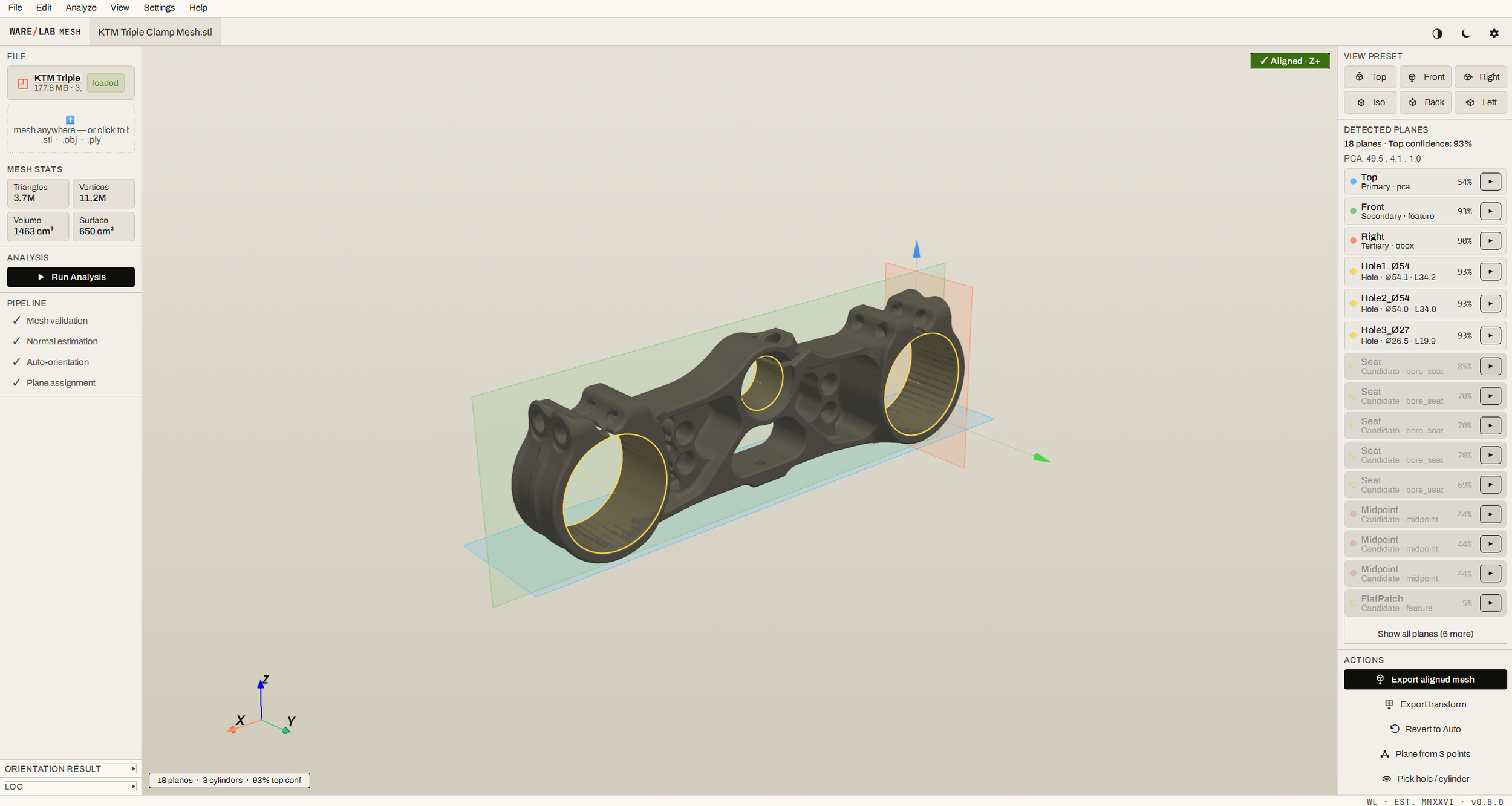
Run Analysis. The tool detects datum planes, bore axes, and symmetry candidates automatically, consolidates fragmented scan patches into clean datum cards, and ranks them by confidence and direction diversity.
Assign the datums. Drag the best card to Top, Front, Right. Or pick manually for anything the auto-detection doesn't handle cleanly.
Set the origin. On a bore centre, a datum intersection, or the symmetry centre — wherever makes sense for the downstream work.
Export. The aligned mesh, at the coordinate position you defined.
The auto-detection step is where most of the time-saving happens. Rather than showing you every detected surface (which on a complex scan can run into dozens of fragmented patches), WARELAB Mesh consolidates coplanar fragments and presents a curated shortlist of the most useful candidates — clean, ranked, and labelled with a confidence reading. A "show all" expander is there for edge cases where you need to dig deeper.
On a production-size part like a triple clamp at 11.2 million vertices, analysis runs in a few seconds. The datum cards are ready before you've finished reading them.
Handling tricky features
Manual Cylinder detection
Auto-detection works well on flat datum faces and prominent bores. It doesn't handle everything equally well — and that's expected. The honest workflow is: auto the obvious, pick the rest.
Manual 3-point planes. For angled flanges, chamfered edges, or any surface where the auto-detection doesn't fire cleanly: click three points on the surface, and a best-fit plane fits to them live. Assign it as Top, or use it as a secondary constraint.
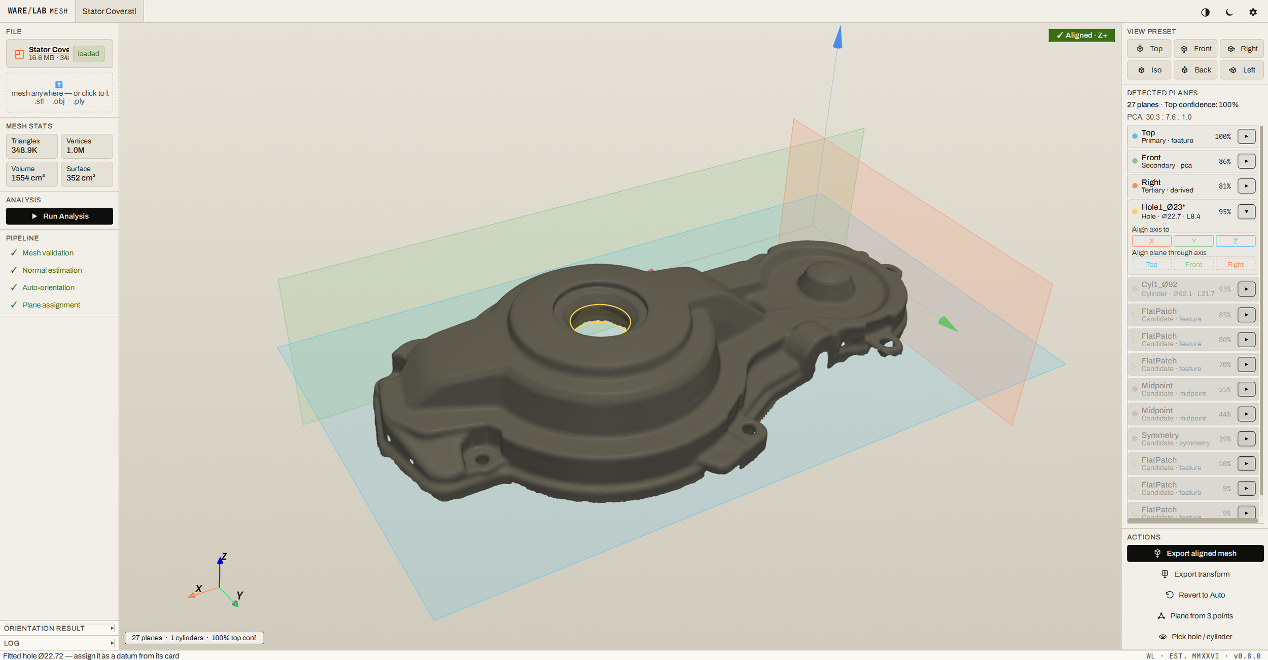
Bore and hole picking. Click a bore and WARELAB Mesh fits a cylinder to it, showing a crisp ring overlay, the cylinder axis, and a fit-quality reading. That axis can be assigned to X, Y, or Z; the bore centre can be set as the coordinate origin. Particularly useful for counterbores, split clamps, and any small or partially obscured hole where auto-detection doesn't trigger.
Bore-seat detection. Version 0.8.0 adds bore-seat detection: flange faces and annular seats adjacent to a bore are promoted to first-class datum candidates rather than being treated as background geometry. On parts like fork legs, pivot pins, or clamp housings, this surfaces the right datum face without manual hunting.
For damaged or worn bores, manual picking works down to partial coverage — the fit-quality readout tells you whether the result is usable.
Checking your alignment
Deviation Analysis
Once the datums are assigned, the obvious next question is: how well does this scan actually sit on that plane?
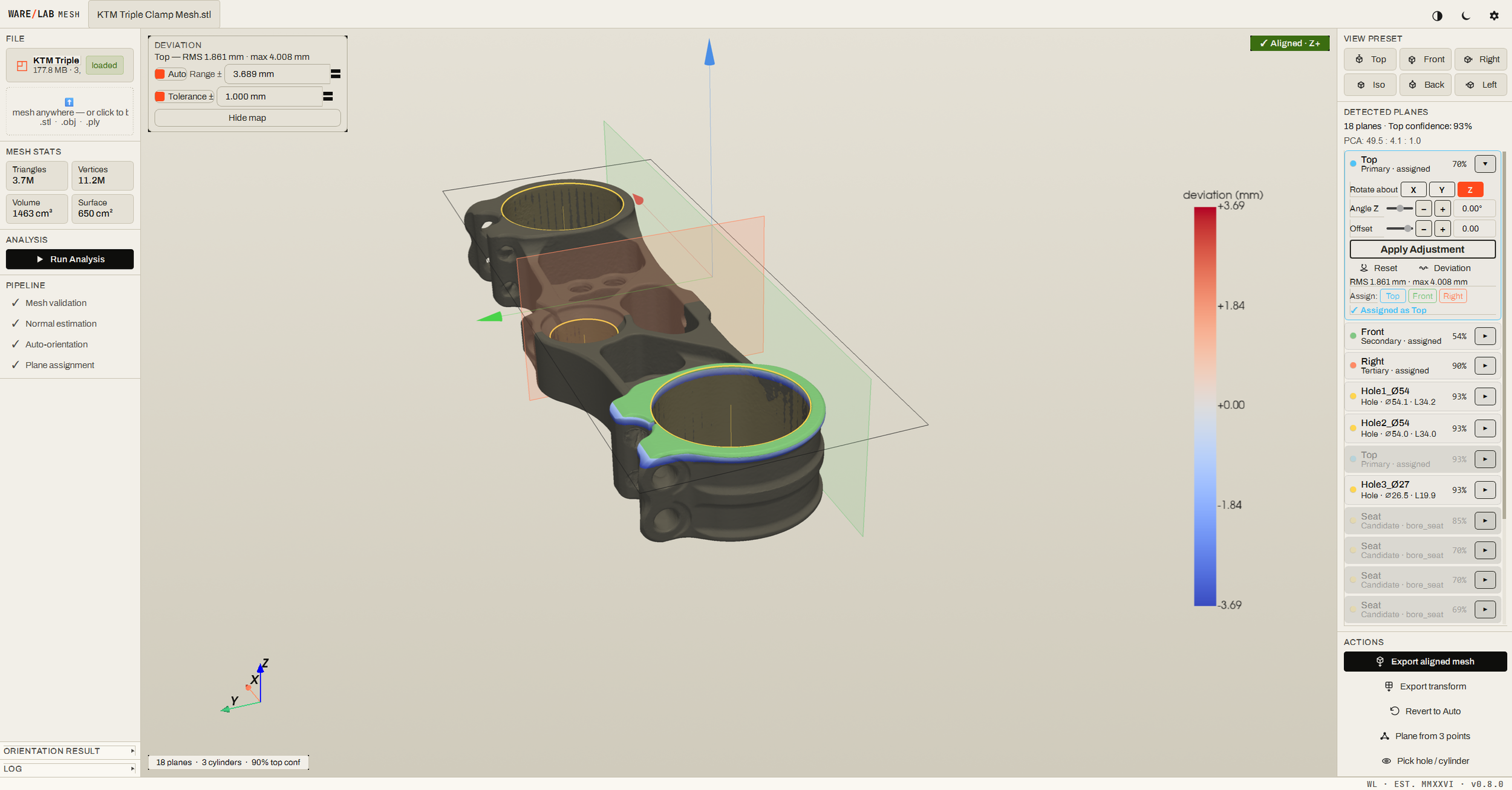
WARELAB Mesh includes deviation tolerance bands for exactly this. Pick a datum card, switch to the Deviation view, and the mesh recolours as a signed-distance heatmap from that plane. Set a tolerance band — say, ±0.1 mm — and the heatmap immediately shows what's in-spec (within tolerance) versus out-of-spec (beyond it). Live RMS and maximum deviation readouts update as you drag the tolerance slider.
This isn't full GD&T — there are no datum reference frames, no MMC modifiers, no formal report output. What it is: a quick, honest pass/fail read on how flat a datum face actually is, and how much deviation your scan has relative to a plane. For most alignment verification and rough dimensional work, that's exactly what's needed.
The heatmap and tolerance toggle work on large scans without delay — on the same 11.2-million-vertex part mentioned above, switching the deviation view on and off is instant.
Working with large scans
Scan file sizes vary enormously. A simple prototype might be a few hundred thousand vertices. A detailed automotive component scanned at high resolution might be 10–20 million vertices or more.
WARELAB Mesh is tested on production-size geometry: analysis runs in the 3–8 second range on an 11.2-million-vertex part; a 22.2-million-vertex scan (around 350 MB) stays responsive throughout. Repeated operations on the same scan — toggling deviation, adjusting datum assignments — use cached derived data and update without delay.
The honest caveat: initial load and analysis is full cost each time. If you're on older hardware, large scans will take longer than on a modern workstation. But the tool won't stall, lock up, or require you to decimate the file before doing anything useful.
Try it yourself
The best test of any alignment tool is your own parts. WARELAB Mesh runs on Windows 10/11 (64-bit), installs in under 130 MB, and comes with a free 7-day trial — export is unlocked for the full trial period.
Version 0.8.0 is the current release: smarter auto-alignment, manual datum and hole-picking tools, a new symmetry engine, deviation tolerance bands, and major large-scan performance improvements.
Download the free trial — warelab.co.uk/download
If you want to see the workflow in motion before downloading, the Version 0.8.0 feature walkthrough covers all five improvements with real part demos.
Built by engineers, for engineers. — George, WARELAB
